

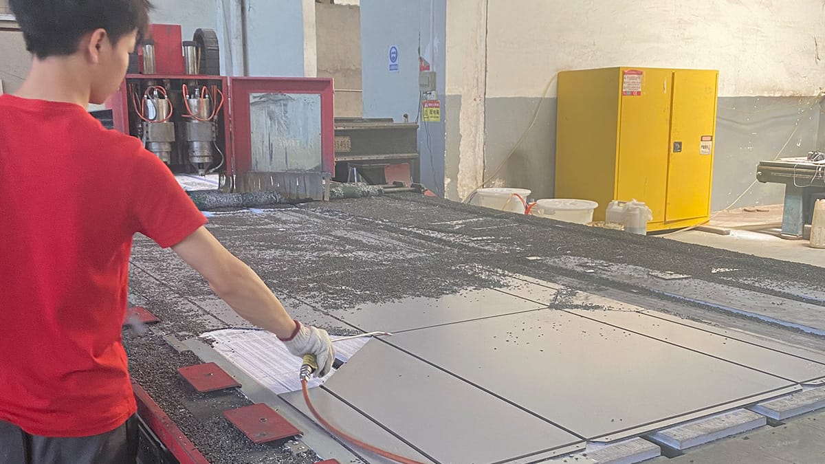
01 Aug ACP Fabrication: CNC Routing, Grooving and Tolerances
ACP fabrication is the controlled conversion of flat aluminum composite panels into installation-ready parts by cutting, CNC routing, V-grooving, drilling, folding, and inspecting against approved drawings. The most important result is not simply a clean cut. It is a finished cassette or component whose dimensions, groove position, fold geometry, surface direction, and fixing points all match the façade or interior system.
A reliable process begins before the router starts. The fabricator must know the panel build-up, aluminum skin thickness, core type, coating face, grain or directional finish, protective-film direction, final part geometry, and agreed tolerances. When these inputs are incomplete, even accurate CNC equipment can repeatedly produce the wrong part.
What ACP fabrication includes
ACP fabrication can include straight cutting, contour cutting, routing, V-grooving, slotting, drilling, notching, folding, corner reinforcement, attachment of stiffeners, and cassette assembly. The exact sequence depends on whether the panel will become a flat sign face, an interior wall panel, a tray, a column cover, or an exterior rainscreen cassette.
The material should first be confirmed against the order and fabrication drawing. A drawing that identifies only the visible panel size is not enough. A fabricator also needs return depths, fold lines, joint locations, fixing zones, cut-outs, datum edges, finish direction, part numbers, and any allowance required by the chosen forming method.
CNC routing, V-grooving and cutting compared
These operations are related but they do different jobs. CNC routing describes the machine-controlled removal of material along a programmed path. V-grooving creates a controlled channel so the panel can fold. Cutting separates the full panel thickness. A single CNC machine may perform all three operations by changing tools and tool paths.
| Operation | Primary purpose | Critical controls | Typical verification |
|---|---|---|---|
| Full-depth cutting | Separate blanks or create final outlines | Datum, kerf allowance, edge support and burr control | Length, width, diagonal and edge quality |
| CNC contour routing | Create curves, openings, notches and complex parts | Tool diameter, compensation, hold-down and nesting | Profile template, hole position and part orientation |
| V-grooving | Remove core material to create a fold line | Groove depth, residual material, tool angle and centerline | Trial fold, inside radius and outside-skin condition |
| Drilling or slotting | Create fixing or adjustment points | Hole size, edge distance and thermal-movement intent | Gauge check and position from the approved datum |
| Folding | Form returns, trays and cassettes | Fold direction, sequence, support and minimum radius | Finished depth, squareness, bow and surface inspection |
Why the groove controls the fold
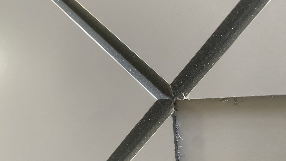
A V-groove removes most of the core and leaves a controlled residual section beneath the outside aluminum skin. This lets the panel bend along a predictable line. If the groove is too shallow, excessive core remains and the fold may be difficult, rounded, or dimensionally inaccurate. If it is too deep, the outer skin or bond line can be damaged, weakening the corner or creating a visible line on the finish.
There is no universal groove depth that should be copied into every drawing. The correct setting depends on total panel thickness, aluminum skin thickness, core behavior, tool geometry, the intended inside radius, coating system, and the manufacturer’s fabrication guidance. A shop should validate the setting with the actual production material, not only with an unrelated scrap panel.
Tool wear also matters. A worn cutter may generate heat, tear the core, leave chips in the groove, or shift the effective geometry. For repeated parts, the first-off sample should be folded and measured before a full nesting run begins. Periodic checks are then used to detect tool wear or movement in the machine setup.
Build tolerances around the finished part
A common mistake is to inspect only the flat routed blank. The installed system uses the folded cassette, so the finished part must be the controlling result. Groove position, residual thickness, material spring-back, fold sequence, return depth, and corner details can all influence the final dimensions.
Tolerances should therefore be assigned by function. The visible joint line may require tighter control than a concealed return. A locating hole may need tighter positional control than a slotted movement hole. The complete assembly also needs enough adjustment to absorb reasonable building and subframe variation without forcing panels into position.
| Characteristic | Control method | Why it matters | Record |
|---|---|---|---|
| Overall cassette size | Measure from the approved datum after folding | Controls joint alignment and module fit | First-off and sampling report |
| Return depth | Check at multiple points | Affects bracket position and panel plane | Part inspection sheet |
| Squareness | Compare diagonals or use a fixture | Prevents tapered joints | First-off record |
| Hole or slot position | Gauge from the same reference edges used by CNC | Controls fixing alignment and movement allowance | Gauge result or coordinate check |
| Surface direction | Check arrows, labels and nesting orientation | Avoids visible shade or grain reversal | Nesting map and label |
| Flatness and twist | Inspect on a known flat support | Controls reflection and final façade appearance | Release inspection |
A controlled fabrication workflow
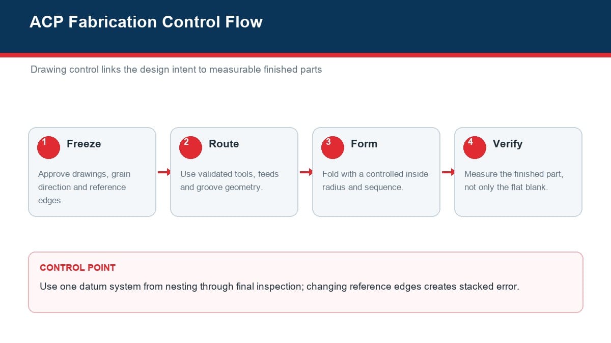
1. Freeze the drawing and datum system
Release a controlled fabrication drawing with a revision number. Identify the face side, finish direction, part number, datum edges, flat blank size, fold lines, returns, cut-outs, holes, slots, and inspection characteristics. If the installation team and factory use different reference edges, dimensions can appear correct individually while the assembled modules drift.
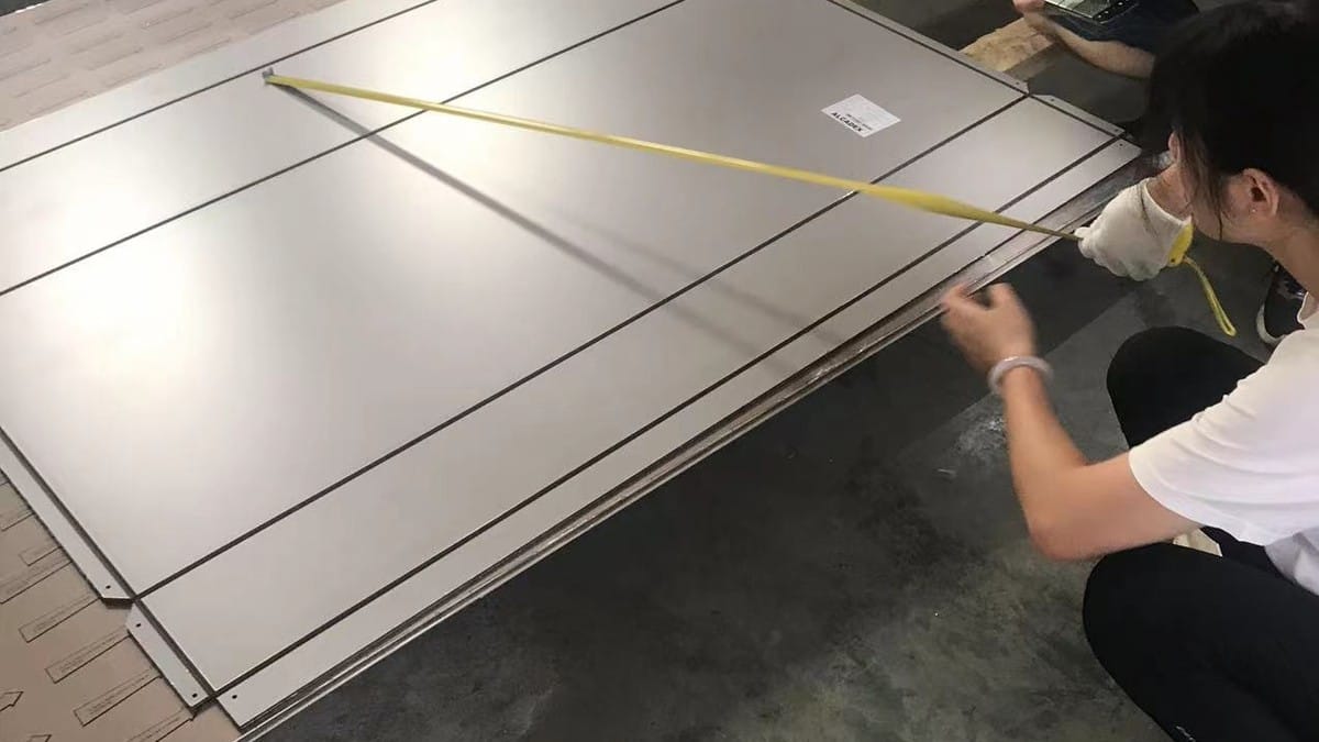
2. Confirm material and create a first-off part
Match the production sheet to the order: total thickness, skin thickness, core type, coating, color, gloss, batch, protective film, and dimensions. Make the first part using the intended program and tools. Fold it in the planned sequence, then inspect the finished geometry and surface before authorizing the complete run.
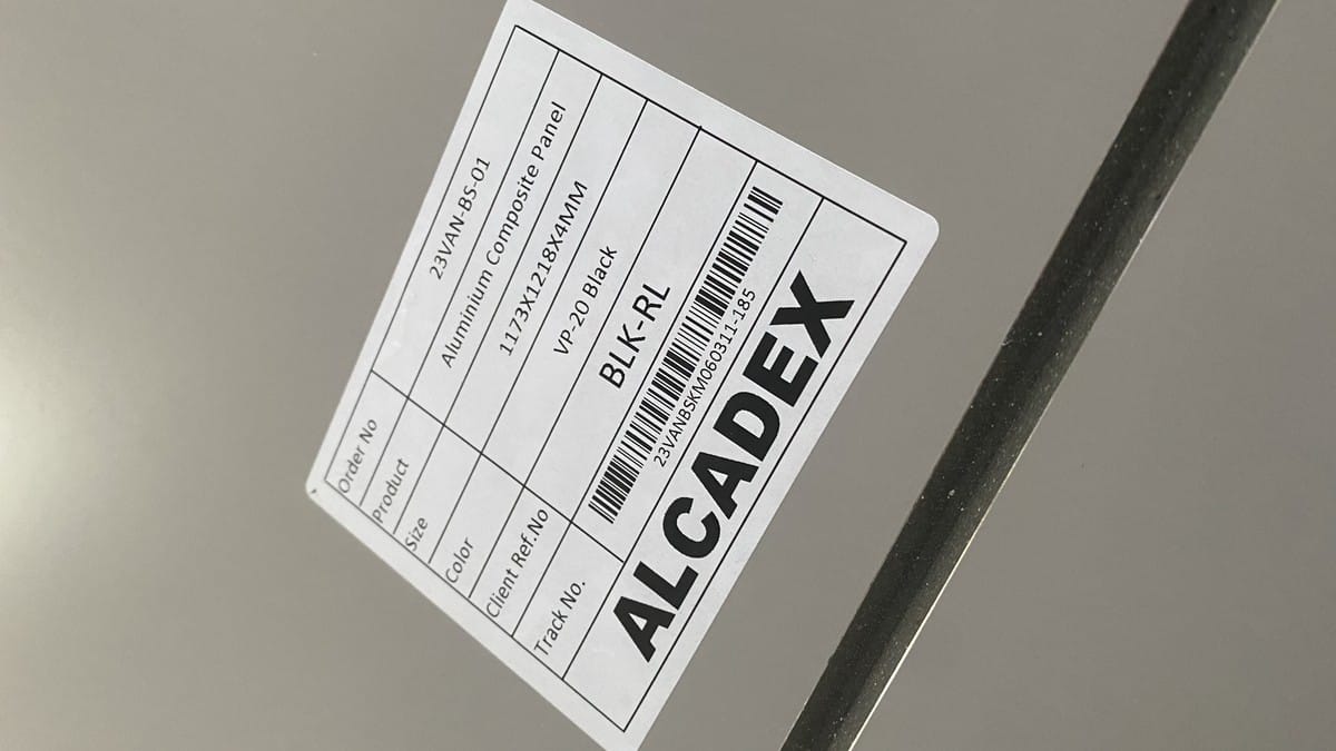
3. Control routing and handling
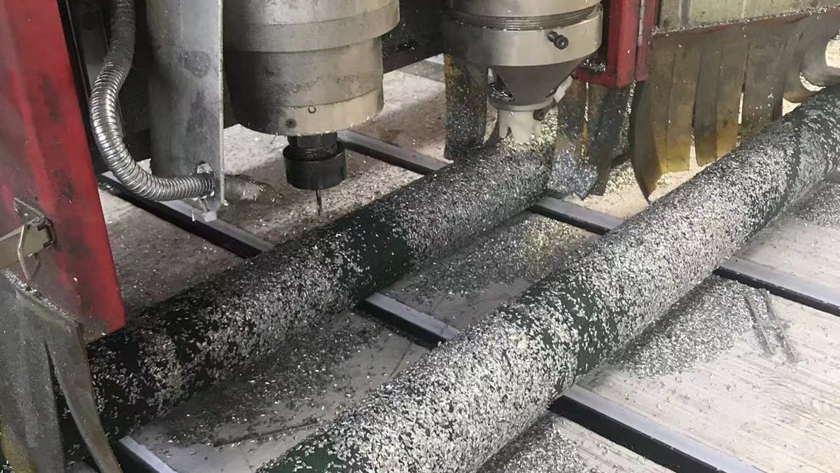
Keep the sheet fully supported and secured. Chips under a panel can dent the finish; poor hold-down can move the part during routing. Confirm tool condition, spindle settings, feed, depth, extraction, and nesting orientation. Protect completed parts from metal chips, sharp edges, dragging, and mixed stacking.
4. Form in a repeatable sequence
Some cassettes cannot be folded in an arbitrary order because one return may obstruct the next. Define the sequence, support the finish face, and use fixtures when repeatability is important. Do not hammer directly on a coated face. After forming, inspect corner quality, return depth, squareness, bow, and any local surface marking.
5. Identify, pack and release
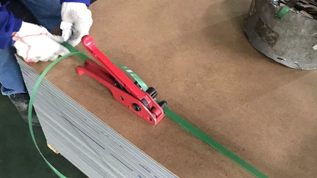
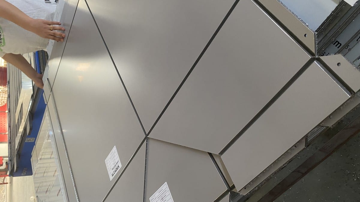
Maintain part identity from nesting to packing. Labels should connect each component to the drawing, façade zone, finish direction, and batch. Pack fabricated components with compatible separators and edge protection. Release them only after inspection records and any nonconformance decisions are complete.
What causes inaccurate ACP parts?
Dimensional problems usually come from a chain of small decisions rather than one dramatic machine failure. Typical causes include an outdated drawing, wrong datum, incorrect tool compensation, sheet movement, groove-depth drift, worn cutters, incorrect fold sequence, inconsistent measuring methods, or mixing nominal and finished dimensions.
Surface defects have a different but overlapping chain. Chips beneath the sheet, dirty supports, excessive heat, careless stacking, premature film removal, incompatible tapes, or dragging finished pieces can turn a dimensionally correct part into a rejected part. A practical control plan treats appearance as a measurable release requirement, not a final cosmetic check.
What to include in an ACP fabrication RFQ
A clear request for quotation prevents suppliers from pricing different scopes. State whether the requirement is sheets only, cut blanks, routed blanks, folded cassettes, or fully assembled panels. Attach controlled drawings and identify the required inspection and packing documents.
| RFQ item | Information to provide | Supplier confirmation |
|---|---|---|
| Panel specification | Thickness, skin, core, coating, color, gloss and finish direction | Exact production build-up and permitted alternatives |
| Fabrication scope | Cutting, routing, drilling, folding, assembly and accessories | Included operations and subcontracted work |
| Drawings | Revision-controlled flat and finished dimensions | Drawing review and manufacturability comments |
| Tolerances | Functional limits for finished components | Measurement method and sampling frequency |
| Identification | Part, elevation, batch and direction labels | Label format and traceability plan |
| Packing | Part sequence, separators, crate limits and shipping mode | Pack design and handling instructions |
Frequently asked questions
Can ACP be routed with ordinary woodworking tools?
Some fabrication operations can use suitable woodworking-type equipment, but the tool, speed, feed, support, extraction and safety controls must match the actual panel. For production work, validate the method with the material supplier and make a trial part.
Should tolerances be measured before or after folding?
Both checks can be useful, but the finished folded component should control the dimensions that affect installation. Flat-blank inspection alone cannot reveal every forming effect.
Does CNC machining guarantee identical panels?
No. CNC improves repeatability only when drawings, datum, programming, tooling, hold-down, material identity and inspection are controlled. It can also repeat an incorrect setup very efficiently.
Can protective film remain on during fabrication?
Often it remains on the visible face for protection, but its condition and supplier instructions must be respected. Chips, heat, damaged film or excessive storage time can still mark the surface or make removal difficult.
Final takeaway
Good ACP fabrication converts design intent into traceable finished parts. The essential controls are a complete drawing, one datum system, verified material, a validated groove and fold setup, first-off approval, in-process checks, finished-part inspection, and careful identification and packing. Buyers who define those controls in the RFQ can compare suppliers on the same basis and reduce expensive rework at the installation stage.
For project-specific ACP builds, fabrication options, and sample review, explore Alcadex aluminum composite panels or contact the Alcadex team with your drawings and performance requirements.