

02 Aug ACP Drilling and Fastening: Edge Distance and Hole Design
ACP hole design must match the fastener, support, load path and thermal-movement strategy. A clean drilled hole can still fail its purpose if it is too close to a cut edge, clamps a panel that must move, misses the subframe or transfers load through an unsupported skin.
For that reason, Alcadex does not treat drilling as a generic diameter-only instruction. The fabrication drawing should distinguish locating holes from movement slots, identify the datum, show the supporting return or reinforcement and state how the selected rivet, screw, bolt or concealed attachment is intended to work.
Round holes and slots do different jobs
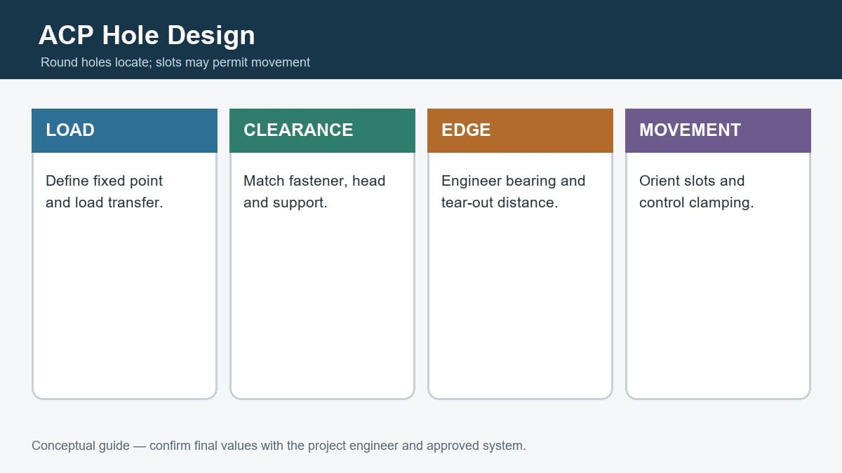
| Feature | Typical role | Main design check |
|---|---|---|
| Close-fit round hole | Locate a component or defined fixed point | Load, bearing, installation tolerance and fastener specification |
| Clearance round hole | Provide assembly tolerance | Washer or head coverage and allowable slip |
| Slotted hole | Allow adjustment or movement in one direction | Slot orientation, length, head coverage and clamping |
| Oversized service opening | Pass a fitting or service | Edge reinforcement, sealing and visible finish |
Step 1: coordinate the fixing design
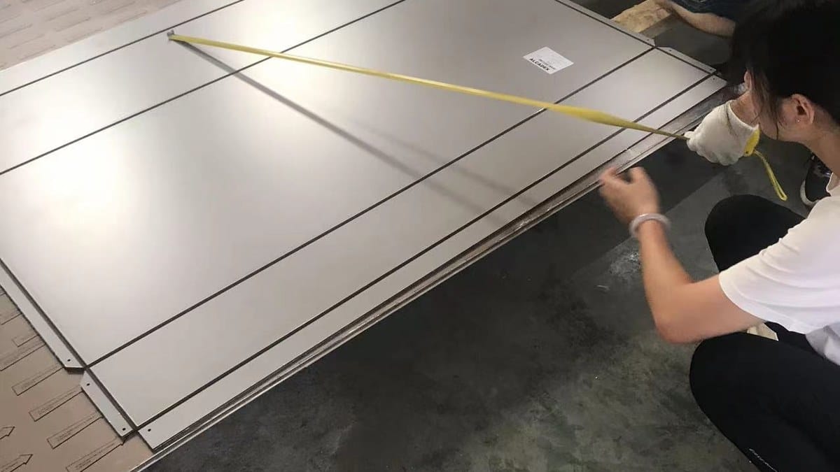
Before drilling, confirm the subframe location, bracket geometry, fixed and sliding points, joint layout and installation access. The drawing should state hole center coordinates from stable datum edges. Dimensions chained from one hole to the next accumulate error and make site alignment less predictable.
Step 2: support and drill the actual component
The component is supported to prevent vibration, surface denting and breakout. The selected tool must produce the intended diameter without dragging swarf across the coating. Drilling through an unsupported folded return can distort the return; machining before forming may be preferable when the drawing datum and fold allowance are controlled.
Step 3: deburr, inspect and protect
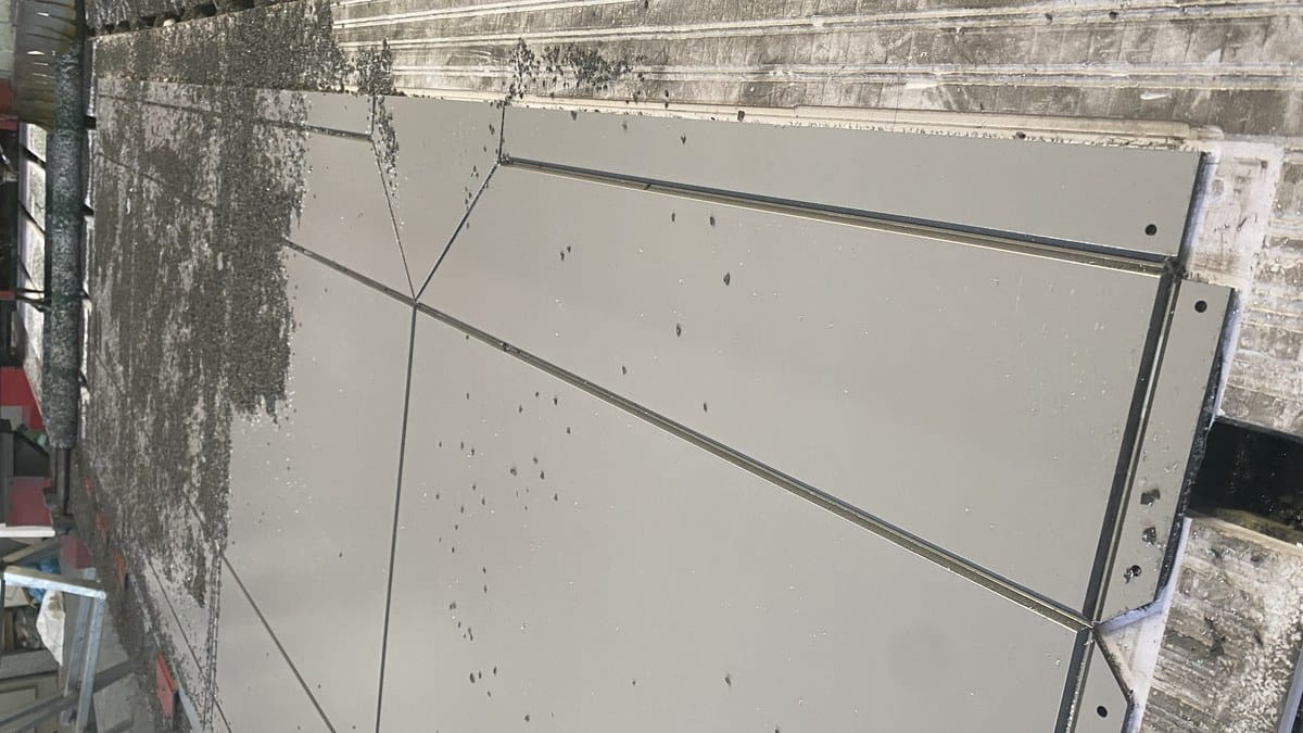
Remove loose burrs and chips without enlarging the hole or scratching the face. Verify diameter, slot length and orientation, location from the datum, edge condition and distance to the cut or fold. Inspect the surrounding coating and protective film. Finished components should be separated so drilled edges cannot mark adjacent faces.
Why edge distance matters
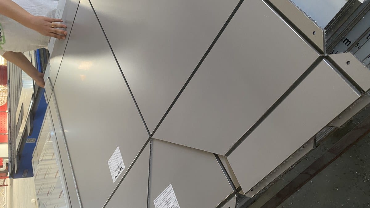
A hole close to an edge leaves less material to resist bearing, tear-out and local deformation. Yet one universal minimum is misleading because performance depends on skin gauge, core, return geometry, fastener diameter, washer or head size, load direction and backing support. The engineer or approved system supplier should define the requirement. Fabrication then verifies that the hole center and finished edge meet it.
Fastener and hole coordination
| Fastener | Useful feature | Hole-related risk | Buyer check |
|---|---|---|---|
| Blind rivet | Fast installation from one side | Grip range, pull-up deformation and movement restraint | Material compatibility, head size and approved grip |
| Self-drilling screw | Simple fixing to suitable metal support | Over-tightening, stripped support or coating damage | Support thickness, torque and sealing detail |
| Bolt with washer | Controlled clamping and larger bearing area | Over-clamping can prevent movement or crush the return | Washer, torque, access and locking method |
| Concealed clip or bracket | Hidden face and system adjustment | Mislocated holes transfer load eccentrically | Approved bracket drawing and installation tolerance |
Thermal movement cannot be drilled away
Aluminum components expand and contract with temperature. A slot can accommodate movement only when it is oriented correctly, covered by the fastener head or washer, and not clamped so tightly that sliding is impossible. The entire façade path—from panel to bracket, rail and structure—must be coordinated. Random oversized holes are not a movement design.
Inspection record for repeat parts
For repeated panels, approve a first-off component and record the machine program revision, tool, material batch and measured coordinates. Use a gauge or coordinate check for critical holes. Sampling frequency should reflect volume and risk. Any tool change, program revision, datum change or material deviation should trigger renewed verification.
Information to put on the RFQ
- Panel thickness, skin gauge, core and coating.
- Finished component drawing and revision.
- Hole or slot size, orientation and coordinate datum.
- Fastener type, head or washer and support material.
- Fixed-point and movement-point logic.
- Critical tolerances and inspection records.
- Surface protection and packing method.
When these items are coordinated before production, drilling supports installation accuracy instead of becoming a site correction exercise.
Galvanic compatibility and exposed cut edges
Fasteners, brackets and aluminum skins may be exposed to moisture, sealants or cleaning chemicals. The system designer should consider galvanic compatibility and isolate dissimilar metals where required. A drilled edge also exposes aluminum and core locally. Whether that edge needs sealing depends on the environment, fixing detail and approved system; it should not be decided by an unrecorded site habit.
Seal washers can help at particular penetrations, but they are not a substitute for a designed weather layer. On a rainscreen, water may pass the outer joint and be managed by the cavity. On a sealed assembly, penetration details may have a different role. The same screw and washer cannot be assumed to suit both.
Site-drilled holes versus factory-drilled holes
Factory drilling offers controlled datum, repeatability and inspection. Site drilling can accommodate surveyed conditions but increases the risk of misalignment, swarf damage and unapproved edge distances. A practical project may use both: factory holes for defined cassette components and controlled site drilling at adjustable interfaces. The shop drawings should show which operations occur where.
If a site hole misses its intended support, adding another nearby hole can create a weakened strip and an unclear load path. The nonconformance should be recorded and reviewed rather than concealed by a larger washer. The engineer can then decide whether a new bracket, reinforcement or replacement component is required.
Frequently asked questions
Can standard twist drills be used on ACP?
Suitable tooling depends on the hole, panel construction and production method. The important result is a clean, correctly located hole without face damage or excessive burrs.
Should movement slots be horizontal or vertical?
The slot follows the intended movement direction, which depends on the fixed point and system layout. There is no universal orientation.
Can a rivet be tightened like a screw?
A blind rivet has its own setting behavior and grip range. The selected rivet and nosepiece must be compatible with the detail and movement intent.
How are hole positions checked on repeated panels?
Use the approved datum, gauges or coordinate measurement on the first-off part, then sample production at the agreed frequency.