

07 Aug What Is Perforated ACP? Uses and Design Limits
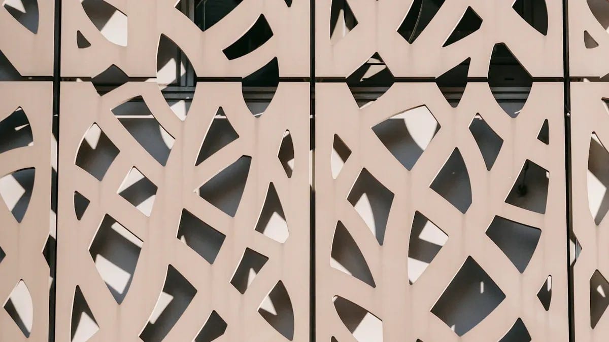
Perforated ACP is aluminum composite panel that has been mechanically cut, punched, drilled, or CNC-routed to create repeated or custom openings through the panel. The openings can form circles, slots, geometric patterns, gradients, logos, or screening effects. Perforation changes appearance, open area, airflow, light transmission, weight, stiffness, edge exposure, and the support required by the panel.
Perforated ACP is not the same as perforated solid aluminum sheet. ACP contains two aluminum skins bonded to a core, while solid aluminum is a single metal sheet or plate. The best choice depends on pattern geometry, bending and welding needs, fire requirements, cut-edge treatment, span, wind or impact loads, and the complete wall or screen system.
How Perforated ACP Is Used
Designers use perforation to create depth, partially screen views, filter daylight, form ventilation openings, conceal services, or introduce a project-specific pattern. Potential applications include interior screens, feature walls, ceiling elements, retail displays, signage backgrounds, equipment enclosures, and selected exterior rainscreen or shading elements.
Suitability is never determined by the pattern alone. An exterior perforated panel may experience local wind pressure, vibration, water entry, thermal movement, and fatigue around openings. An interior panel may still require safe edges, impact resistance, fire compliance, cleanability, and a secure support system.
Perforated ACP vs Solid ACP and Solid Aluminum
| Comparison | Perforated ACP | Solid ACP | Perforated Solid Aluminum |
|---|---|---|---|
| Construction | Two aluminum skins, bonded core, and openings through the composite | Two aluminum skins and bonded core without designed openings | One aluminum sheet or plate with openings |
| Visual effect | Pattern, transparency, shadow, filtered light, and layered graphics | Continuous color, image, texture, or flat cladding surface | Pattern and transparency with exposed all-metal edges |
| Cut edges | Openings expose the composite build-up and require project-specific review | Usually limited to perimeter cuts, routes, folds, and joints | Expose aluminum only and may be deburred, coated, or finished |
| Forming | Possible routing and folding depend on remaining material and panel design | Commonly routed and folded into cassettes | Can support more extensive metal forming and welding, depending on alloy and thickness |
| Stiffness after perforation | Reduced as material is removed; composite action around openings must remain reliable | Highest continuity for the same original ACP specification | Depends on metal thickness, pattern, folds, ribs, and frame |
| Selection priority | Pattern feasibility, edge condition, core, supports, coating, and fabrication quality | Panel specification, coating, core, cassette, joints, and supports | Alloy, thickness, forming, finish, corrosion, welds, and support design |
When the design needs deep folds, welded corners, very small bridges between holes, or fully metallic exposed edges, solid aluminum may be more suitable. When the design needs a lightweight flat decorative face with controlled perforation, ACP may be considered after technical review. Ask the fabricator to confirm the exact material instead of using “perforated panel” as a generic specification.
Key Perforation Design Variables
Hole or opening geometry
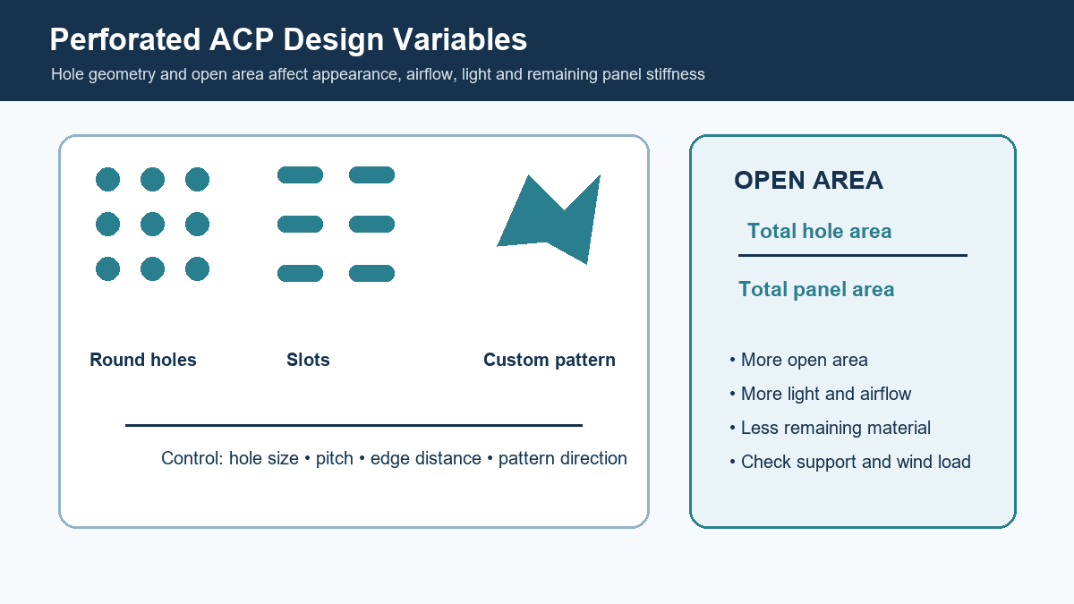
Round holes distribute stress differently from long slots or sharp-cornered shapes. Custom motifs can create very narrow ligaments between cuts. Internal corner radii, cutter diameter, and entry points should be included in the design. A line drawing that looks clean on screen may contain shapes that are fragile or impractical to route at full scale.
Pitch and bridge width
Pitch is the center-to-center spacing of repeated openings. Bridge width is the material remaining between adjacent openings. Small bridges may bend, vibrate, crack, or expose inconsistent edges. The required minimum depends on panel construction, cutter, pattern, support, load, and fabrication trials; it should not be guessed from a decorative rendering.
Edge distance
Openings need adequate distance from panel edges, folds, routes, fasteners, brackets, and joints. If a perforation cuts too close to a fixing, the remaining material may not distribute load reliably. The designer should identify protected fixing zones in the pattern file.
Open area
Open area is the percentage of the patterned field removed by openings. A larger open area can increase transparency and airflow but leaves less material to carry load. It also changes the appearance from different distances. Open area should be calculated from the final geometry, not estimated from a rendering.
What Perforation Changes in an ACP Panel
Removing material reduces the effective section and interrupts the panel’s continuous skins and core. This can increase local deformation and make the panel more sensitive to handling. Large openings can leave strips that behave independently. Wind or air pressure can also act on the remaining solid area and cause vibration.
Perforation does not automatically create a safe ventilation grille. The free area, pressure drop, insect or rain screen, equipment clearances, acoustic requirement, and fire strategy must be designed for the complete opening. Likewise, a patterned panel does not automatically provide effective solar shading; orientation, depth, open area, sun angles, and distance from glazing matter.
Cut Edges, Core Exposure, and Coating
Every opening exposes a cut edge. On ACP, that edge can reveal aluminum skins, bonding layers, and core. The project team should decide whether the appearance is acceptable and whether a compatible treatment is required. Small perforations may be difficult to seal consistently. Added coatings or sealants must not create stains, block holes, attack the core, or compromise fire documentation.
Pre-coated panels are normally cut after the face coating is applied, so the inside of a routed opening does not carry the same factory face finish. Solid aluminum may allow different post-fabrication finishing routes. This is a major selection difference and should be reviewed on a physical prototype.
Protective film can help during fabrication but must be compatible with the process and removed within the supplier’s recommended conditions. Cutter heat, chips trapped under film, blunt tools, and poor vacuum extraction can scratch or smear the finish.
Fire and Code Considerations
Perforation does not give ACP a fire classification, and a classification for a solid panel may not automatically cover a perforated screen or the complete installed assembly. The core, panel construction, cavity, insulation, membrane, supports, joints, openings, barriers, and building use all matter.
Exterior walls, escape routes, ceilings, equipment screens, and public interiors can have different requirements. Specify the required test standard and classification, then ask whether the proposed perforated construction is within the documented scope. The authority having jurisdiction and responsible fire consultant should review the final system.
Acoustic and Ventilation Expectations
A perforated face by itself is not an acoustic absorber. Sound absorption usually depends on the open area, hole geometry, cavity depth, backing material, air gap, mounting, and frequency range. If acoustic performance is required, use tested assembly data or obtain an acoustic design for the exact build-up.
Ventilation performance also belongs to the whole system. Free area differs from gross opening area, and pressure loss depends on pattern, thickness, screens, louvers, filters, and airflow. Coordinate perforated panels with the mechanical engineer instead of relying on a visual percentage.
From Pattern File to Approved Prototype
- Define the base panel. State size, total thickness, aluminum skins, core, coating, color, and application.
- Map structural and fixing zones. Mark folds, rails, brackets, fasteners, joints, and no-cut areas.
- Create a fabrication-ready vector file. Use closed paths, defined radii, dimensions, panel references, and pattern direction.
- Review manufacturability. Confirm cutter size, minimum bridges, edge distances, tolerances, nesting, film, and handling.
- Produce a representative prototype. Include the smallest bridges, largest openings, folds, edges, finish, and real fixing detail.
- Inspect and test. Check burrs, delamination, flatness, appearance, vibration, load, fire scope, airflow, or acoustics as required.
Alcadex lists cutting, punching, grooving, and CNC machining among its processing capabilities. Submit the actual drawings for review because capability depends on the panel, pattern, tolerance, and project requirements.
Pattern Scale, Viewing Distance, and Lighting
A pattern that looks dense on a computer screen can appear almost solid from across a street, while a motif designed for a façade may look coarse at arm’s length. Prepare elevations at scale and evaluate printed or physical samples from the actual viewing distances. Include the structure and cavity behind the openings, because a bright backing, dark void, membrane, insulation, or lighting source changes the perceived pattern.
Daylight produces moving shadows that depend on sun angle and panel offset. Artificial backlighting can reveal cutter variation, support rails, wiring, and dirt behind the screen. If illumination is part of the design, prototype the real light source, diffusion layer, cavity depth, access, heat management, and cable route. Avoid representing a backlit render as proof of the built result.
Pattern repeats must align across joints when visual continuity is required. Number panels and include common setting-out origins in the fabrication files. Where each panel uses a unique gradient or image, the schedule should prevent rotation or swapping. Add grain or coating direction arrows when the base finish is directional.
Fabrication Quality Checks
Before a production run, confirm the machine program, tool type, cutter condition, feed, speed, support bed, extraction, and protective-film method on the specified panel. The fabricator should inspect entry and exit quality, burrs, skin lifting, core smearing, coating chips, heat effects, dimensions, and flatness. The acceptance sample should include the most demanding geometry rather than only easy large holes.
After machining, loose chips and dust must be removed without scratching the face. Panels should be supported during lifting because perforated fields can be more flexible than solid sheets. Interleaving, edge protection, rigid pallets, and clear stacking limits reduce transport damage. If panels arrive in installation sequence, durable labels can save considerable site handling.
Tolerances should distinguish overall panel dimensions, hole size, hole position, pattern position, joint alignment, folds, and fixing locations. A general tolerance for the whole part may not protect a pattern that must align through several panels. State which datum controls the pattern and how cumulative deviation will be managed.
Maintenance and Inspection
Openings collect dust and make both sides of a screen more visible. The design should provide safe access for cleaning and inspection without requiring workers to bend fragile bridges. Exterior cavities need drainage and should avoid trapping leaves or debris. Bird or insect screens, if required, change airflow and appearance and must be coordinated early.
Inspect supports, fasteners, vibration, edge condition, coating damage, sealants, and local distortion at intervals suited to the environment. A panel near mechanical exhaust, salt spray, road pollution, or frequent public contact may need a different maintenance plan from a high-level interior feature. Use cleaners compatible with the face coating and any exposed edge treatment.
Perforated ACP Specification Checklist
| Specification Item | Information Required | Why It Matters |
|---|---|---|
| Application and location | Interior/exterior, height, exposure, viewing distance, and access | Sets environmental, safety, and maintenance priorities |
| Base ACP | Size, thickness, aluminum skins, core/fire requirement, coating, color, and gloss | Defines the material before perforation |
| Pattern geometry | Vector file, hole shapes, dimensions, pitch, radii, direction, and open area | Controls appearance and manufacturability |
| Protected zones | Edge distance, folds, routes, joints, fasteners, rails, and no-cut areas | Preserves fixing and support capacity |
| Engineering | Panel spans, loads, deflection criteria, vibration, and support details | Perforation reduces the remaining load path |
| Cut-edge requirement | Accepted exposed edge, treatment, color, and prototype standard | ACP openings reveal the composite build-up |
| Performance evidence | Fire, acoustic, airflow, weather, impact, or other required verification | These properties belong to the complete assembly |
| Commercial details | Quantity, processing, labels, packing, Incoterm, destination, and date | Needed for a comparable quotation and safe delivery |
Common Design Mistakes
- Specifying “perforated ACP” without stating the base panel construction.
- Using a perforated-metal reference image as proof that ACP will produce the same edge or forming result.
- Finalizing the pattern before locating folds, rails, brackets, and fasteners.
- Leaving bridges too narrow or openings too close to panel edges.
- Assuming open area alone proves ventilation, shading, or acoustic performance.
- Ignoring how exposed core edges will look and weather.
- Skipping a full-size prototype with the actual cutter, finish, and support detail.
- Assuming a solid-panel fire document automatically covers the perforated assembly.
Frequently Asked Questions
What is perforated ACP?
It is an aluminum composite panel with designed openings cut or machined through the face skins and core to create patterns, partial transparency, airflow, or decorative effects.
Can ACP be perforated with custom patterns?
Yes, subject to the panel construction, cutter, opening geometry, bridge widths, edge distances, tolerances, support layout, and prototype approval.
Is perforated ACP suitable for exterior façades?
It may be suitable as part of an engineered exterior system. Coating, core, cut edges, wind, vibration, water, thermal movement, supports, joints, fire requirements, and maintenance must all be reviewed.
Does perforated ACP absorb sound?
Not by itself. Acoustic performance depends on the complete tested or designed assembly, including the openings, backing absorber, cavity, mounting, and frequency range.
Is perforated ACP the same as perforated aluminum sheet?
No. ACP is a bonded composite with a core; solid aluminum is one metal layer. Their cut edges, forming options, stiffness, fire documentation, and finishing routes differ.
Request a Perforation Feasibility Review
Send Alcadex the base ACP specification, application, vector pattern, panel layout, fixing zones, folds, quantities, performance requirements, edge expectations, packing, and destination. A drawing-based review and representative prototype are the safest way to confirm what can be produced.
Contact Alcadex to discuss perforated ACP patterns, CNC processing, samples, and a project quotation.