


25 Aug ACP Cavity Ventilation, Drainage and Condensation
ACP cavity ventilation is the controlled movement of air behind aluminum composite panel cladding, coordinated with drainage openings, a weather-resistive layer and the complete exterior wall design. Its purpose is not to make an ACP sheet waterproof by itself. A successful cavity gives incidental water a route out, supports drying where the design requires it and keeps moisture-control layers continuous around joints, openings and transitions.
The required cavity depth, opening area, membrane, insulation position, fire-stopping and condensation strategy depend on the project climate and wall assembly. These are system-design decisions for the appointed façade and building-envelope professionals. The ACP supplier can provide panel information, but the panel alone does not determine wall drainage or hygrothermal performance.
Drainage, Ventilation and Condensation Control Are Different
These terms are often grouped together, but each describes a separate function. Drainage removes liquid water. Ventilation or venting exchanges air with the exterior where the approved system uses that approach. Condensation control manages temperature, vapor movement, airtightness and drying across the complete wall build-up.
| Function | What it manages | What must be coordinated |
|---|---|---|
| Drainage | Rainwater that passes the outer cladding layer or reaches an interface | Downward path, flashings, outlets, drips and clear base conditions |
| Ventilation or venting | Air exchange and drying potential in the designed cavity | Openings, cavity continuity, insect protection and compartment boundaries |
| Water-resistive layer | Water that reaches the backup wall side of the cavity | Membrane laps, penetrations, window transitions and substrate preparation |
| Air and vapor control | Air leakage and vapor flow through the wall assembly | Climate, indoor conditions, material sequence and continuity |
| Thermal control | Surface temperatures and thermal bridges that influence condensation risk | Insulation, brackets, slab edges, openings and project analysis |
A cavity can drain without being designed for continuous airflow, and a nominal air gap does not automatically provide useful ventilation. The approved drawings should state the intended wall concept rather than using “ventilated façade” as a general marketing label.
Map the Complete ACP Rainscreen Cavity
A typical exterior arrangement may include a backup wall, membrane, insulation, brackets and rails, a cavity and formed ACP panels. The order and details vary. Reviewers should trace both the water path and the load path without allowing one system layer to block the other.
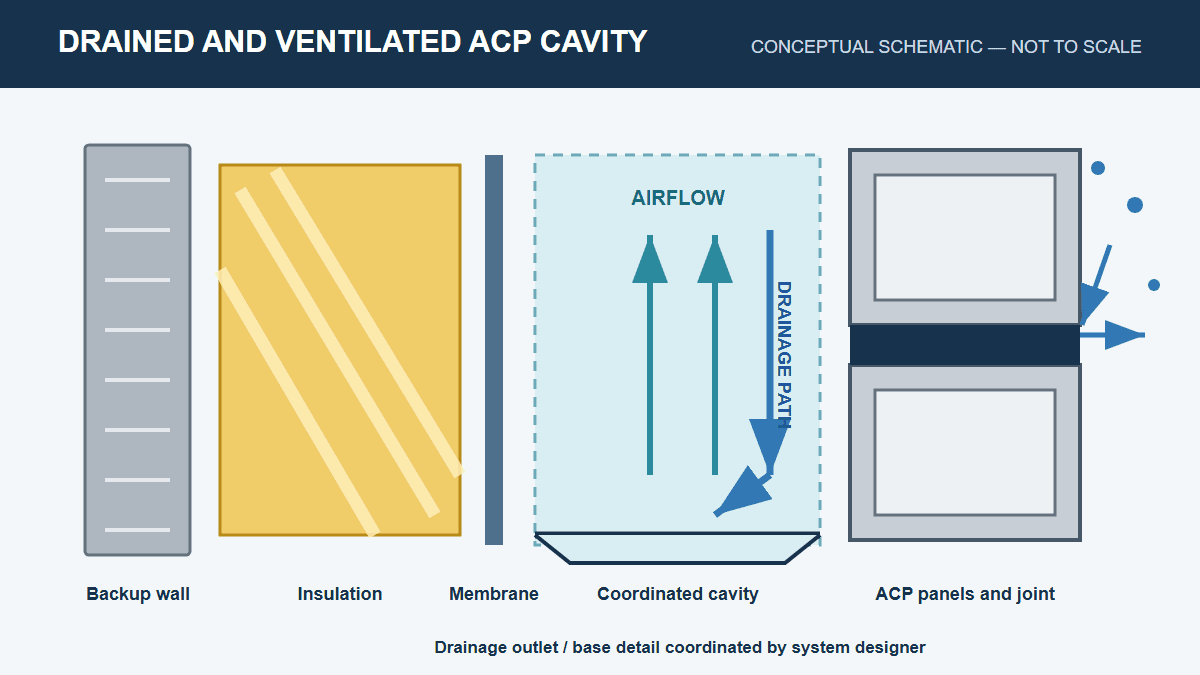
The outer ACP layer sheds most direct rain, but joints and interfaces should be designed on the assumption that some water may reach the cavity. The backup weather layer then provides a second line of control. Its continuity is especially important where brackets, fasteners, windows, doors, parapets and service penetrations interrupt the field of the wall.
Subframe components must fit within this arrangement. Rails should not unintentionally dam water, and brackets should not create unresolved membrane penetrations. Alcadex’s guide to ACP subframes, rails and alignment explains the related load-path and tolerance questions.
Design Panel Joints as Part of the Water Strategy
ACP joints establish the façade pattern, allow fabrication and installation tolerances, and interact with the moisture-control concept. Open joints, baffled joints, gasketed joints and sealed joints manage water differently. The system designer should define which joint type applies at each condition and how water reaching the joint is directed.
Sealant should not be treated as a substitute for the complete drainage strategy. Where sealed joints are specified, joint geometry, substrate preparation, backing material, adhesion and movement capability must be coordinated. Read ACP sealant compatibility and joint design for the buyer information needed before approving sealant-related details.
Joint width also interacts with thermal and building movement. A narrow visual joint cannot safely absorb every fabrication, installation and movement demand. The approved layout should coordinate joint dimensions with panel modules, rail movement and building joints. For further context, see ACP expansion joints and thermal movement.
Keep the Drainage Path Continuous
Water in a drained cavity needs a downward route and a defined exit. Horizontal rails, stiffeners, sealant, insulation edges and fire barriers can interrupt that route if the details are not coordinated. Each interruption should either shed water outward or connect to another approved drainage path.
Base details should discharge water away from vulnerable wall layers and finished surfaces. Drips, flashings and outlets need sufficient projection and continuity for the project condition. Avoid concealed pockets where debris, sealant or construction residue can block the intended exit.
At intermediate levels, shelf angles, slab edges or compartment details may change the drainage route. The drawing should show whether each cavity section drains independently and where its water exits. Do not assume that water can travel uninterrupted from the parapet to the building base.
Plan Ventilation Openings and Cavity Continuity
If the approved system uses ventilation, air must enter and leave through intentional openings. The cavity needs continuity between those openings while respecting fire, acoustic and compartment requirements. Screens or perforated closures may help limit insects or debris, but they also affect free opening area and require coordination.
Rails, brackets and insulation should not reduce the cavity below the designed condition. Installation variation matters: insulation that bows outward or loose membrane material can obstruct a narrow gap. The project QA plan should include checks before the panels conceal the cavity.
More airflow is not automatically better. Excessive or uncontrolled openings can conflict with pressure, fire, pest or weather objectives. The building-envelope professional should select the venting concept for the climate, building height and wall assembly rather than copying a detail from an unrelated project.
Evaluate Condensation at the Wall-System Level
Condensation occurs when moisture reaches a surface at a temperature low enough for water to form. In an exterior wall, risk can be influenced by outdoor climate, indoor temperature and humidity, air leakage, vapor diffusion, insulation continuity, thermal bridges and material sequence. The ACP skin is only one exterior layer within that analysis.
Air leakage can transport far more moisture through gaps than designers expect from material diffusion alone. Air-barrier continuity around windows, slab edges, penetrations and transitions is therefore a key coordination issue. A ventilated cavity cannot compensate for uncontrolled moist air entering the wall from the interior.
Brackets and rails may create thermal bridges through insulation. Their effect depends on material, geometry, spacing and the complete wall build-up. Project-specific thermal and hygrothermal analysis may be needed; a general blog article or panel datasheet cannot determine condensation safety for a building.
Resolve Openings, Corners, Bases and Parapets
Typical wall sections are not enough. Most water-management problems occur at terminations and transitions. Review window heads, jambs and sills; doors; louvers; internal and external corners; bases; parapets; roof transitions; signage; lighting; balconies and service penetrations.
| Interface | Drawing questions | Common coordination risk |
|---|---|---|
| Window or door head | Where does cavity water discharge, and how does the membrane connect to the frame? | Water is directed behind the opening flashing |
| Sill | Is there an outward fall, end control and clear drip? | Water collects at corners or returns inward |
| Parapet | How do coping, membrane and cavity termination overlap? | Top entry bypasses the drained cavity strategy |
| Building base | Where are drainage and ventilation openings, and are they protected? | Landscaping, paving or sealant blocks the outlet |
| Penetration | How do membrane, flashing and panel trim connect to the penetrating item? | Independent trade work breaks membrane continuity |
| Material transition | Which system receives and drains water from the adjacent assembly? | Two acceptable typical details create an unacceptable junction |
Coordinate Cavity Barriers and Fire-Safety Details
Cavity barriers and fire-stopping can divide the cavity and alter both airflow and drainage. Their locations, supports, seals and interfaces must follow the project’s approved fire strategy. Drainage routes should be detailed around each compartment without weakening the required barrier.
Do not infer façade fire performance from an ACP core label alone. Panel construction, insulation, membranes, cavity products, barriers, subframe and installation all contribute to the complete assembly. Product test information should be reviewed within the specific project approval process.
Control Materials, Staining and Water Traps
Water can carry dust, metal residue, uncured materials or sealant by-products onto visible surfaces. Specify compatible membranes, sealants, flashings, fasteners and closures, and avoid details that discharge dirty water across the panel face. Protective film should not remain as an uncontrolled construction membrane or block a designed outlet.
Dissimilar metals and persistent moisture can increase corrosion risk at concealed components. Material compatibility, isolators and protective finishes should suit the actual exposure. The system designer should also avoid unvented pockets that trap water around brackets, cut edges or fasteners.
Review the Cavity Before Releasing Panels
Shop drawings should connect panel codes and joints to the concealed wall layers. Enlarged details are needed wherever the water, air or thermal-control line changes direction. Refer to Alcadex’s ACP shop drawing coordination checklist when preparing the review package.
| Release item | Evidence to review | Responsible coordination |
|---|---|---|
| Wall concept | Approved sections showing cladding, cavity, membrane, insulation and backup wall | Building-envelope designer |
| Water path | Joints, flashings, intermediate drainage and outlets at every termination | Façade designer and architect |
| Air and vapor control | Continuous control layers and project-specific condensation assessment | Envelope professional |
| Subframe interfaces | Bracket penetrations, rail orientation and clear cavity dimensions | Façade engineer and installer |
| Fire compartments | Approved barrier locations, support, sealing and drainage interfaces | Fire and façade professionals |
| Inspection access | Hold points and records before panels conceal the cavity | Contractor and project QA team |
Inspect and Maintain the Intended Openings
During construction, inspect the membrane, flashings, cavity width, drainage paths, ventilation openings and interfaces before the ACP panels close access. Photograph concealed conditions and record corrections against current drawings. Remove debris that could block outlets or retain water.
After completion, maintenance teams should keep designated openings clear and investigate staining, repeated wetting or water discharge in unexpected locations. Sealant replacement or façade alterations should not close vents or redirect water. Repairs must preserve the original approved wall strategy.
Common Cavity Coordination Failures
- No defined secondary water layer: the outer ACP face is assumed to stop all water.
- Blocked drainage: rails, insulation, sealant or debris interrupt the downward path.
- Disconnected details: typical sections work, but windows, parapets or material transitions do not.
- Uncontrolled openings: vents are added without checking weather, pest, pressure or fire requirements.
- Air leakage mistaken for ventilation: moisture enters the wall from unintended interior gaps.
- Panel-only condensation claim: wall performance is predicted without climate, indoor conditions or full material layers.
- No concealed-work inspection: panels cover missing membrane laps or blocked outlets before they are recorded.
Frequently Asked Questions
Does every ACP façade require the same cavity depth?
No. Cavity depth depends on the approved wall system, subframe, drainage and ventilation concept, insulation, movement, fire strategy and project tolerances.
Are open panel joints enough to ventilate the cavity?
Not automatically. Effective air exchange depends on intentional inlet and outlet geometry, cavity continuity and the complete design. Open joints can also admit water, so drainage and the backup weather layer remain important.
Can a ventilated cavity prevent all condensation?
No. Condensation depends on climate, indoor moisture, air leakage, vapor flow, temperatures and the complete wall build-up. Project-specific assessment may be required.
Who should approve ACP cavity details?
The responsible architect, façade engineer, building-envelope professional and other project-appointed reviewers should approve the applicable system details. Supply responsibilities must be stated in the contract.
Coordinate ACP Supply with the Wall-System Design
When requesting Alcadex aluminum composite panels or fabricated cassettes, provide approved panel layouts, joint types, returns, fixing zones, finish specifications and the defined interface with the cavity and subframe. Confirm which drawings, clips or fabrication services are included in the quotation.
Contact Alcadex for product information, samples and a quotation based on your panel specification. Project-appointed professionals remain responsible for drainage, ventilation, condensation analysis, fire-safety interfaces and approval of the complete exterior wall system.