

21 Aug ACP Shop Drawings: Panel Codes, Joints and Coordination
ACP shop drawings translate approved design intent into coordinated panel layouts, fabrication information and installation references. A useful package identifies every panel, fixes the controlling dimensions, defines joints and interfaces, and records revisions before material is cut. It should let the architect, façade engineer, fabricator and installer review the same information without relying on assumptions.
Shop drawings are coordination documents, not a substitute for engineering. Project-appointed professionals must still approve structural loads, anchors, subframes, fire-safety details, waterproofing and regulatory compliance. The panel supplier should only confirm product information that falls within its documented supply scope.
What Should an ACP Shop Drawing Package Include?
A complete package usually combines general notes, elevations, panel schedules, enlarged details and fabrication information. The exact sheet set depends on the façade system and contract, but reviewers should be able to trace each installed position from the elevation to a unique panel record.
| Drawing section | Information to show | Reviewer check |
|---|---|---|
| Cover and general notes | Project, drawing index, applicable specifications, material scope, finish references and drawing conventions | Current project information and a clearly defined scope |
| Panel elevations | Grids, levels, opening positions, panel joints, panel codes, finish zones and orientation | Alignment with approved architectural elevations |
| Panel schedule | Unique code, finished size, blank size where applicable, quantity, color, grain direction and revision | No duplicate or untraceable panel identities |
| Typical and enlarged details | Joints, corners, returns, parapets, bases, openings, transitions, drainage paths and interfaces | Buildable continuity at every condition |
| Fabrication details | Cutouts, grooves, folds, holes, stiffeners, brackets and visible-face orientation | Information is sufficient for controlled production |
The package should also state what is excluded. For example, an ACP fabricator may provide panel fabrication drawings while the façade contractor or engineer remains responsible for the supporting system and anchor design. Recording that boundary prevents a coordination drawing from being mistaken for a structural calculation.
Confirm the Inputs Before Drafting
Drafting should begin from controlled documents, not from an early visual concept. Assemble the latest architectural elevations, sections and details; the approved material specification; structural or façade-system information; finish approvals; door and window schedules; interface details; and relevant site measurements. Record each source revision in a drawing register.
Resolve inconsistencies before completing the panel layout. A window dimension on an elevation may differ from the opening shown on a section. A parapet detail may have changed without the panel elevation being updated. If the drafter quietly chooses one source, the conflict is transferred to fabrication or installation. A request for information should identify the discrepancy and obtain a documented answer.
Use Unique Panel Codes and Clear Orientation
Every fabricated panel needs a unique code that follows it through the drawing, schedule, production record, label, package and installation location. A code can combine elevation, level, zone and sequence, provided the convention is explained and remains stable. For example, a project may use an elevation letter, floor number and panel sequence rather than a generic number that repeats across multiple façades.
Panel orientation matters even when dimensions appear symmetrical. Metallic finishes, brushed surfaces, wood patterns and other directional finishes may look inconsistent if adjacent panels are rotated. The drawing and schedule should show a visible-face arrow or grain direction, while fabrication information should distinguish the visible face from the back face.
| Panel record field | Purpose | Risk if unclear |
|---|---|---|
| Unique panel code | Connects location, fabrication and packing records | Wrong panel delivered to the wrong position |
| Finished dimensions | Defines the installed panel geometry | Joint width or alignment varies |
| Cut blank dimensions | Controls material cutting before grooves and folds | Returns cannot be formed to the intended size |
| Finish and batch reference | Links the panel to the approved appearance | Color, gloss or texture mismatch |
| Direction arrow | Preserves the approved visual orientation | Adjacent panels reflect light differently |
| Revision and status | Shows whether the record is approved for production | An obsolete panel is fabricated |
Do not reuse a retired code for a different geometry. If a panel changes after review, retain a visible revision trail and update the corresponding schedule, fabrication file and label data together.
Separate Controlling Dimensions from Reference Dimensions
Shop drawings should make clear which dimensions control fabrication. Distinguish the architectural module, joint centerline, finished panel face, cut blank and formed cassette. A note such as “dimensions govern; do not scale drawing” is useful only when the required dimensions are actually present and consistent.
Use project grids, levels or agreed datums so installers can relate the panel layout to the building. Avoid long chains of dimensions that accumulate tolerance. Where site construction can vary, identify dimensions that require field verification and state who will provide confirmation.
Tolerances also need a coordination strategy. Panel fabrication tolerance, subframe position, opening tolerance and installation adjustment are different items. They should not all be absorbed by changing the visible joint. The project team should establish how the system accommodates variation while maintaining alignment.
Coordinate Joint Width, Movement and Drainage
Joint lines are part of both the architectural appearance and the façade system. Show the intended joint width, panel edge condition and relationship to supporting components. Identify whether the joint is sealed, gasketed or open, and show how water is managed behind the visible surface.
Movement provisions should be coordinated with panel dimensions, support spacing and adjacent construction. Long elevations, corners, material transitions and building movement joints require particular attention. The drawing should not show a continuous rigid condition where movement is expected. For a focused overview, see Alcadex’s guide to ACP expansion joints and thermal movement detailing.
Do not assume that a sealant line alone defines waterproofing. The complete project detail should establish cavity drainage, flashing, membranes and interfaces with windows, doors, roofing and other cladding. Those system decisions must be approved by the responsible designer.
Translate the Layout into Fabrication Information
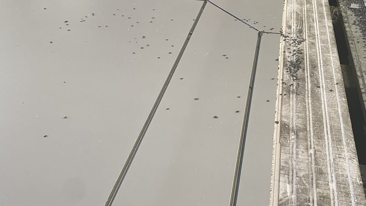
A panel elevation is not automatically a fabrication drawing. The production team needs unambiguous information for the flat blank and the formed part. Show groove lines, fold directions, return depths, corner treatments, cutouts, holes, stiffeners, brackets and other components within the agreed scope.
For routed and folded panels, the drawing should connect the finished face dimension to the groove location and return geometry. Groove depth and remaining material influence the fold, so they require controlled production settings rather than an assumed line on a drawing. Review the related ACP V-grooving and fold-quality inspection guide when defining inspection points.
The detail level should match the assembly method. A cassette system may require returns, corner reinforcement, brackets and fixing zones that do not apply to a flat sheet. Alcadex’s overview of ACP cassette returns, fixings and design checks explains the coordination questions buyers should resolve before production.
Review Every Interface, Not Only the Typical Bay
Typical elevations often look complete while edge conditions remain unresolved. Review external and internal corners, parapets, soffits, bases, floor lines, door and window perimeters, louvers, signage, lighting, penetrations and transitions to other materials. A drawing package should show how panel codes and joints continue—or intentionally stop—at these interfaces.
Openings deserve special attention because several trades meet there. Confirm the structural opening, frame position, membrane or flashing, insulation continuity, drainage path, panel return and acceptable sealant geometry. Coordinate MEP penetrations and signage supports before panel release; adding them later can damage coating, remove necessary material or conflict with stiffeners.
Use enlarged details for conditions that cannot be understood from the elevation. If a corner has different left- and right-hand parts, assign distinct panel codes rather than depending on an installer to infer orientation.
Control Review Status and Revisions
A drawing package should move through defined statuses. “Submitted,” “reviewed with comments” and “released for fabrication” are not interchangeable. The team should name the person or organization authorized to release production and define how review comments are closed.
| Drawing status | Permitted action | Required control |
|---|---|---|
| Draft / coordination | Resolve layout, dimensions and interfaces | Keep separate from production data |
| Submitted for review | Architect, consultant and responsible engineer review applicable scope | Log comments by drawing and revision |
| Revise and resubmit | Incorporate and answer review comments | Cloud or otherwise identify changes |
| Approved / released | Create controlled fabrication data for the approved scope | Record approval, date, revision and release authority |
| Superseded | Reference only; no fabrication or installation | Remove from active folders and mark visibly |
Revision control must reach the shop floor. Updating a PDF without replacing the cutting file, panel schedule or printed labels creates parallel versions. A release register should identify the approved drawing set and every associated production file. If an approved change affects panels already cut, quarantine the affected parts until the disposition is documented.
Connect Drawings to Labels, Packing and Installation
The panel code is most valuable when it remains traceable after fabrication. Labels should be readable without damaging the finished face and should correspond to the drawing schedule. Packing lists can group panels by elevation, floor or installation sequence, reducing unnecessary handling on site.
For overseas projects, packing information should also help the receiver reconcile crates or pallets with the panel schedule. The shop drawing package does not replace a packing specification, but the two records should share consistent panel identities. See the Alcadex guide to ACP pallets, cases and surface protection for related buyer checks.
Common ACP Shop Drawing Errors
- Repeating panel codes: identical labels are assigned to different elevations or mirrored parts.
- Mixing dimension types: the finished face, cut blank and opening size are shown without clear labels.
- Missing finish direction: directional panels are rotated during nesting or installation.
- Unresolved interfaces: typical bays are detailed, but corners, openings and parapets are left to site interpretation.
- Drawing-scale fabrication: a missing dimension is inferred by measuring a printed or exported drawing.
- Uncontrolled revisions: an updated elevation is issued while the schedule or machine file remains obsolete.
- Undefined responsibility: a supplier’s panel drawing is incorrectly treated as approval of anchors, subframes or waterproofing.
Pre-Release Checklist for Buyers and Project Teams
Before authorizing fabrication, confirm that the drawing package and commercial order describe the same material. Product thickness, aluminum skin specification, core or fire classification, coating, color, gloss, finish direction and quantity should match the approved submittal and purchase order. Alcadex’s ACP technical submittal guide provides a companion document checklist.
- All source drawings and site dimensions use recorded revisions.
- Every panel has one unique code and one defined location.
- Finished size, blank size and visible-face orientation are clearly distinguished.
- Joint widths, datums and alignment lines are coordinated across elevations.
- Corners, openings, bases, parapets and material transitions have buildable details.
- Fabrication information covers grooves, folds, returns, cutouts, holes and attachments within scope.
- Structural, fire-safety, waterproofing and regulatory approvals remain with the designated professionals.
- Comments are closed, the approved revision is identified and production release is documented.
- Panel labels and packing records use the same codes as the released schedule.
Send Better Information with Your ACP Inquiry
If you are sourcing aluminum composite panels or fabricated panel parts, send the latest drawings, panel schedule, finish reference, required dimensions, quantity and clearly defined supply scope. Identify which dimensions are verified and which still depend on site coordination.
Contact Alcadex to discuss panel material and fabrication requirements. A controlled, coordinated drawing package helps our team review manufacturability and quotation inputs without replacing the project professionals responsible for system design and approval.