

06 Sep ACP Coating Thickness: Dry Film Measurement
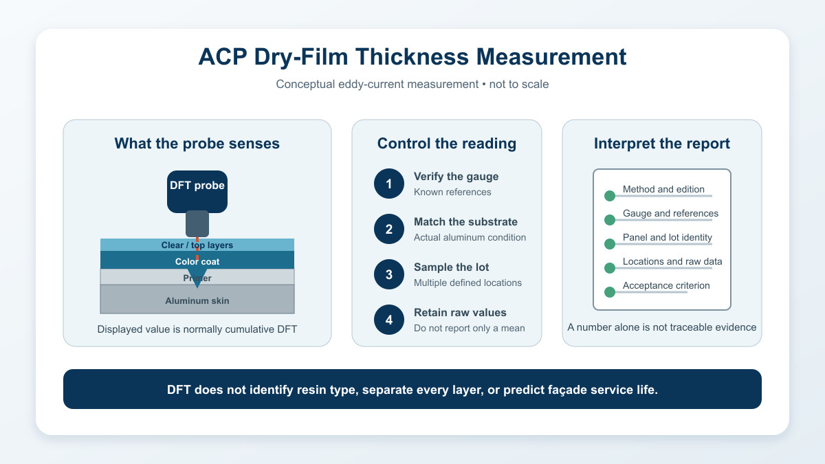
ACP coating thickness is the dry-film thickness (DFT) of the finished organic coating above the aluminum skin, normally expressed in micrometers (µm) or mils. On coated aluminum, a suitable eddy-current gauge can usually measure the cumulative nonconductive coating thickness without cutting the panel. A meaningful result depends on the specified coating system, a representative substrate, verified instrument settings, multiple readings and a written acceptance rule—not one isolated number.
Buyers should distinguish coating DFT from total panel thickness and aluminum skin thickness. A supplier can meet the nominal panel thickness while the coating report remains incomplete, and a DFT reading cannot by itself identify the resin, separate every coating layer, confirm weathering performance or prove suitability for a particular façade.
Which thickness is being measured?
An aluminum composite panel contains several dimensions that serve different purposes. The finished panel thickness affects rigidity, fabrication and system detailing. Each aluminum skin has its own thickness. The organic coating on the exposed face is much thinner and requires a different measurement method.
| Thickness term | What it describes | Typical inspection approach | Common mistake |
|---|---|---|---|
| Total panel thickness | Complete sandwich from front face to back face | Suitable caliper or thickness instrument under an agreed method | Treating it as proof of either aluminum skin thickness |
| Aluminum skin thickness | Metal facing before or after coating, as defined in the order | Material records and an agreed physical measurement method | Subtracting nominal core thickness from a finished panel without accounting for tolerances |
| Total coating DFT | Cumulative dry nonconductive coating above the conductive aluminum | Appropriate eddy-current gauge or another specified method | Assuming one reading represents the complete coil or production lot |
| Individual coating-layer thickness | Primer, color coat and clear coat where present | Process records, destructive sectioning or another agreed layer-specific method | Assuming a handheld total-DFT reading separates each layer |
| Pretreatment or conversion layer | Very thin surface preparation beneath the organic coating | Process control and a method suitable for that layer | Assuming a field DFT gauge can resolve every very thin conversion coating |
The purchase order should say whether a coating requirement applies to the exposed face, reverse coat or both. It should also identify whether the number means an individual reading, a spot result, an average, a minimum average, or another defined statistic. These terms are not interchangeable.
How non-destructive ACP dry-film measurement works
Aluminum is electrically conductive and nonmagnetic. For a nonconductive paint or polymer coating on aluminum, an amplitude-sensitive eddy-current instrument is a common non-destructive option. The probe creates an alternating electromagnetic field, and the instrument relates the response to the distance between the probe and the conductive base metal.
ISO 2360:2017 specifies non-destructive measurement of nonconductive coatings on nonmagnetic, electrically conductive base metals using amplitude-sensitive eddy-current instruments. The ISO scope includes paints and varnishes but notes that the method is not applicable to every conversion coating.
ASTM D7091-22 covers magnetic and eddy-current gauges for dry-film thickness measurement. Its published description emphasizes calibration, verification and adjustment, together with correct measurement practice. For an aluminum ACP face, the user must select or confirm the non-ferrous/eddy-current mode rather than assuming a dual-purpose gauge chose correctly.
The displayed value generally represents the total nonconductive distance sensed above the aluminum substrate. If an ACP face has pretreatment, primer, color coat and clear coat, a handheld reading normally does not identify each component separately. A buyer who needs layer-by-layer evidence should request the appropriate production records or a specified cross-sectional method.
Relevant standards serve different purposes
Standards should be named precisely in the RFQ and report. ISO 2808 provides a broader framework for determining coating-film thickness and describes wet-film, dry-film and uncured powder methods. ISO 2360 focuses on an eddy-current method for nonconductive coatings on conductive nonmagnetic base metals. ASTM D7091 addresses the use and control of dry-film thickness gauges on ferrous and non-ferrous metals.
| Reference | Primary scope | Relevance to coated ACP aluminum | What it does not set automatically |
|---|---|---|---|
| ASTM D7091-22 | Practice for non-destructive DFT measurement with magnetic and eddy-current gauges | Supports instrument control and readings on non-ferrous metallic substrates | The project-specific minimum, maximum or sampling acceptance rule |
| ISO 2360:2017 | Amplitude-sensitive eddy-current measurement of nonconductive coatings on nonmagnetic conductive base metals | Directly relevant to many organic coatings on aluminum | Coating identity, durability class or product approval |
| ISO 2808:2019 | Methods for determining wet, dry and uncured-powder film thickness | Helps the parties select and describe an appropriate film-thickness method | A universal ACP coating thickness |
| Project or coating specification | Defines the required coating system and acceptance criteria | Controls what the supplier must deliver for the stated application | Reliable evidence unless the test method, locations and reporting terms are also defined |
The official ISO 2808:2019 film-thickness standard was confirmed as current in 2026. A report should cite the exact standard and edition used. Writing only “tested by international standard” does not allow a buyer to reproduce or compare the result.
Why ACP coating thickness readings vary
Coating thickness is not perfectly uniform across a coil or panel. Application conditions, film flow and cure can create real variation, while the gauge, probe placement and substrate can introduce measurement variation. The inspection plan therefore needs several readings at defined locations rather than a single favorable value.
| Influence | Possible effect on the reading | Practical control |
|---|---|---|
| Gauge calibration and verification | An instrument can appear precise while carrying a systematic offset | Follow the governing standard and manufacturer instructions; verify before, during and after the inspection as required |
| Substrate alloy, conductivity and thickness | A setup established on a different metal may not represent the ACP skin | Use a representative uncoated base or approved reference approach for the actual substrate |
| Curvature and surface geometry | Probe seating changes on curved, formed or narrow areas | Measure on representative flat areas unless a validated geometry-specific procedure is defined |
| Edges and nearby discontinuities | The electromagnetic field can be influenced near an edge or cutout | Define an edge exclusion distance using the instrument guidance and approved method |
| Probe angle and pressure | Tilt, rocking or inconsistent contact can increase scatter | Seat the probe perpendicular to a clean surface and train operators for repeatable placement |
| Surface cleanliness | Protective-film residue, dust or debris adds separation or prevents stable contact | Use a clean, undamaged test area and record whether protective film was removed |
| Coating texture or metallic effect | Surface profile and coating composition may affect repeatability | Verify the instrument on the actual finish and use an agreed number of readings |
| Temperature and instrument stabilization | Changing conditions may influence electronics or references | Condition the equipment and samples as required by the method and manufacturer |
The thin aluminum facing used in ACP deserves particular attention. A gauge suitable for a thick laboratory plate is not automatically suitable for the actual skin construction. The inspector should verify the instrument’s substrate-thickness range and adjustment procedure using the specific panel or a representative uncoated sample.
Calibration, verification and adjustment are different
These terms are often used loosely, but a traceable report should distinguish them. Calibration establishes the relationship between instrument response and reference values, typically under controlled conditions and often by the equipment manufacturer or a qualified laboratory. Verification checks whether the gauge is reading within an acceptable tolerance on known references. Adjustment changes the gauge response for the substrate, geometry or operating conditions of the work.
A calibration certificate alone does not prove that readings taken on an ACP panel were valid. The operator still needs appropriate verification standards, a representative substrate and the correct instrument settings. Conversely, pressing a “zero” button on a coated panel is not a substitute for a controlled verification and adjustment process.
Foils or shims can help verify a gauge over a relevant range, but their behavior and use must follow the selected standard and instrument instructions. The report should identify the references used, their nominal values, the substrate used beneath them and the verification results. That record makes later supplier comparisons much more defensible.
One reading is not a production-lot result
ASTM D7091 notes that coating thickness can vary widely across a surface and that a single point may not represent the coating system. For ACP procurement, the parties should define how many panels, locations and readings form a spot or sample result. They should also agree how averages, individual limits and retests will be handled.
A useful location plan distributes measurements across panel width and length, avoids unapproved edge zones, and distinguishes exposed face from reverse coat. For coil-coated material, the inspection lot should connect to a traceable production or shipment reference. For fabricated cassettes, the report should say whether readings were taken before or after routing and forming.
Do not average away an important local deficiency unless the governing specification explicitly permits it. A high reading in one area does not necessarily compensate for a low reading elsewhere. Report individual values, defined spot results and the final lot decision so the acceptance logic remains visible.
How to interpret a DFT report
Begin with the ordered coating system, not the measured number. Confirm the coating family, finish, exposed face, number of coats where specified and the controlling product or project requirement. Then check that the test method and instrument principle are appropriate for nonconductive coating on aluminum.
Next, compare the report’s sampling language with the purchase requirement. “Average thickness” is incomplete if the report does not show the individual readings, measurement locations and treatment of unusually high or low values. The units must also be consistent: one mil equals 25.4 micrometers, but repeated conversions and rounding can create apparent discrepancies.
Finally, separate DFT from other finish evidence. Coating thickness does not identify whether the finish is PE, PVDF, FEVE or another resin system. It also does not replace adhesion, color, gloss, weathering or corrosion testing. For adjacent quality checks, see Alcadex guides to crosshatch adhesion testing and ACP Delta E color measurement.
ACP coating inspection report checklist
| Report field | Why buyers need it | Minimum useful detail |
|---|---|---|
| Order and lot identity | Connects the evidence to supplied material | Purchase order, item, color, finish, batch or traceable lot reference |
| Panel configuration | Prevents applying one result to a different construction | Panel type, coated face, aluminum substrate and relevant dimensions |
| Coating system | Provides the context for the DFT requirement | Declared coating family and coat structure without unsupported universal claims |
| Standard and edition | Makes the method identifiable | Complete designation such as ASTM D7091-22 or the contractually selected alternative |
| Instrument | Shows whether the principle suits aluminum | Manufacturer, model, probe and eddy-current/non-ferrous mode |
| Calibration, verification and adjustment | Supports measurement traceability | Reference standards, representative substrate, check values and timing |
| Sampling plan | Defines what the reported result represents | Panels sampled, locations, readings per location and edge exclusions |
| Raw readings and calculations | Prevents averages from hiding distribution | Individual values, spot values, averages, units and rounding rule |
| Acceptance criterion | Separates measurement from the pass/fail decision | Minimum, maximum, average and individual-reading rules as applicable |
| Disposition | Documents action on nonconforming material | Acceptance, quarantine, retest or approved concession with authorization |
When comparing quotations, give every supplier the same reporting template. A statement such as “PVDF coating: 25 µm” may describe a nominal target, a minimum, an average or a copied catalogue value. Requiring the fields above turns the number into auditable procurement evidence.
What dry-film thickness does not prove
A thicker reading is not automatically a better coating. The coating formulation and cure must be designed for the applied film build. Excessive thickness can create its own processing or appearance risks, while an adequate total DFT can still conceal an incorrect layer distribution. The approved coating supplier’s system and the project specification remain controlling.
DFT also does not predict a fixed service life. Exposure, color, gloss, orientation, cleaning, fabrication, edge treatment, sealants and installation details all affect field behavior. An ACP coating decision should combine thickness evidence with the finish specification and other required test reports.
Existing Alcadex content on PVDF coating technical specifications provides broader coating-system context. This DFT guide has a narrower purpose: helping buyers judge whether a thickness measurement and its report are comparable, traceable and appropriate for the ordered material.
Frequently asked questions
Can a magnetic coating gauge measure ACP paint?
A magnetic-induction mode is intended for magnetic substrates such as steel. Aluminum is nonmagnetic, so coated ACP aluminum normally requires a suitable eddy-current or non-ferrous mode. A dual-purpose gauge may switch modes automatically, but the operator should confirm the selected principle and verify it on a representative substrate.
Can the gauge measure primer and topcoat separately?
Not usually in one ordinary non-destructive reading when all layers are nonconductive. The gauge normally senses the cumulative distance to the conductive aluminum. Layer-specific evidence requires appropriate process records or another agreed measurement method.
Should protective film remain on the panel during measurement?
No, not when the objective is the coating DFT beneath it. Protective film adds another nonconductive layer and can distort the result. Use an approved test area, remove the film without contaminating or damaging the finish, and record the sample condition.
Is one average enough to accept an ACP shipment?
Only if the governing specification defines that exact sampling and acceptance approach. A defensible report normally retains individual readings, locations and calculated results so low or high areas are not hidden by one average.
What is the correct DFT for every ACP coating?
There is no single universal value for all ACP finishes. The requirement depends on the specified coating system, supplier documentation, intended application and project standard. Confirm the final coating construction and acceptance criteria in the quotation and technical submittal.
Final takeaway
Reliable ACP coating-thickness control begins by defining exactly what DFT means for the ordered finish. Use a method appropriate for nonconductive coating on aluminum, verify and adjust the gauge on a representative substrate, collect enough readings to represent the lot, and retain the raw data with a written acceptance rule.
If you are preparing an ACP quotation or technical submittal, send Alcadex the required coating family, color, finish, application, film-thickness method, sampling plan and acceptance criteria. Contact Alcadex to align the requested documentation with the exact panel configuration before production.