

24 Aug ACP Subframes: Rails, Alignment and Tolerances
ACP subframes are the rails, brackets, anchors and related support components that transfer loads from aluminum composite panels to the building structure while establishing the façade plane. They also provide the adjustment needed to coordinate panel joints, openings, cavity depth and installation tolerances. The correct arrangement must be engineered for the project rather than selected from panel thickness alone.
The panel supplier can confirm panel construction and fabrication requirements, but the project-appointed façade or structural professional remains responsible for support design, loads, anchors, corrosion strategy, fire-safety interfaces and local approval. Buyers should therefore review the panel and subframe as connected scopes without treating them as the same product.
What Does an ACP Subframe Need to Do?
A subframe creates a controlled connection between an uneven or moving building substrate and a regular panel layout. It must provide a defined load path, keep the visible façade aligned and accommodate the project’s intended movement strategy. It also has to coexist with insulation, membranes, drainage paths, openings and adjacent cladding.
| Subframe function | Information to define | Buyer or reviewer question |
|---|---|---|
| Transfer loads | Panel connection, rail spans, bracket positions, anchors and structural substrate | Who is responsible for calculations and connection approval? |
| Establish the façade plane | Datums, offsets, bracket adjustment and rail alignment | How will substrate variation be measured and corrected? |
| Coordinate movement | Fixed and movement points, rail joints and connection slots | Where can movement occur without loading the panel incorrectly? |
| Maintain cavity interfaces | Cavity depth, insulation, membranes, ventilation, drainage and fire-stopping zones | Do brackets or rails obstruct another system layer? |
| Support installation sequence | Panel codes, fixing access, adjustment sequence and inspection hold points | Can installers verify and record the concealed work? |
No single rail profile or bracket spacing is suitable for every project. Wind actions, panel module, cassette geometry, rail span, substrate strength, building height, edge zones and connection details all influence the final design. The project team should obtain calculations and approved shop drawings for the complete support arrangement.
Understand the Subframe Layers and Load Path
A typical arrangement may include anchors fixed to the structural wall or edge beam, adjustable brackets, vertical or horizontal rails and panel-specific clips or fasteners. Insulation and membranes often occupy the space between the structure and the back of the panel. The visible cladding joint may open into a drained cavity, or it may form part of another approved joint strategy.
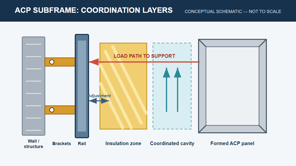
Trace the load path in the drawings. A panel connection transfers actions to a rail; the rail transfers them to brackets; brackets and anchors transfer them to the verified substrate. Any component shown without a defined connection leaves a gap in responsibility. The substrate itself may require testing or project-specific verification before anchors are selected.
Rail direction is not merely a drafting preference. It affects panel support locations, joint layout, bracket access and the way components accommodate movement. Horizontal and vertical rails can both be part of valid systems, but their suitability depends on the complete engineered arrangement and panel fabrication method.
Coordinate Rails, Brackets and Anchors
Rails
Rails create the reference lines to which fabricated panels are attached. Shop drawings should identify profile type, orientation, splice locations, support spacing and connection points. They should also show where a rail stops or changes direction at corners, openings and building movement joints.
Brackets
Brackets connect rails to the structure and commonly provide adjustment in one or more directions. Their geometry must fit the cavity depth without crushing insulation or interfering with membranes. Bracket positions should be coordinated with structural edges, reinforcement information, embedded items and zones where drilling is restricted.
Anchors and fasteners
Anchors are selected according to the verified substrate and engineered actions, not simply by diameter or catalog appearance. Fasteners within the subframe must also match the connection purpose, material combination and movement strategy. For the panel-side options, Alcadex’s guide to ACP rivets, screws and concealed clips explains the purchasing differences between visible and concealed connections.
Set Datums Before Adjusting the Façade Plane
Alignment should begin with agreed project datums, grid lines and finished-face offsets. Survey the relevant substrate before releasing bracket settings or panel dimensions. A rail that is locally straight can still be wrong if it does not relate to the common façade plane.
Use the subframe’s approved adjustment range to correct verified variation. Do not assume unlimited adjustment, stack improvised shims or force rails into position. If the substrate lies outside the designed range, the responsible designer should approve a corrective detail before work proceeds.
Check more than a single rail. Review straightness along each rail, relative alignment between neighboring rails, the overall façade plane and joint datums around openings. Record measurements at defined hold points so problems are found while the subframe remains visible and adjustable.
Plan for Tolerance Without Sacrificing Joint Control
Several tolerances meet at the finished façade: structure position, anchor location, bracket adjustment, rail fabrication, rail installation, panel fabrication and panel fixing. The visible joint should not become an uncontrolled reserve for every upstream variation.
| Tolerance source | Control method | Do not assume |
|---|---|---|
| Structural substrate | Survey against approved grids, levels and façade offsets | The as-built surface matches the design model |
| Anchor and bracket position | Use approved setting-out and adjustment details | Any hole or bracket offset is acceptable |
| Rail alignment | Check line, level, plumb, plane and adjacent-rail relationship | Straight individual rails guarantee a flat façade |
| Panel fabrication | Inspect finished dimensions, returns and fixing locations | The subframe can correct an incorrectly formed panel |
| Visible joints | Set joint centerlines from common datums and approved modules | Joint width can absorb all cumulative error |
The shop drawing package should state which dimensions control, where field verification is required and what happens when a measured condition is outside the accepted range. Read the related guide to ACP shop drawings and panel coordination before releasing fabrication data.
Coordinate Thermal and Building Movement
Rails, panels and the building structure can move differently as temperature and loads change. The engineered connection strategy should identify fixed points, movement points, rail splices and panel joints. Slots or sliding connections must have a defined direction and purpose; they should not be treated as a universal correction for inaccurate setting-out.
A movement joint in the building should not be bridged by a rigid cladding support unless the responsible designer has detailed that condition. Rail lengths, splice gaps and panel modules should be coordinated so movement is not locked into the system. For additional design questions, review ACP expansion joints and thermal movement detailing.
Protect the Cavity, Drainage and Insulation Strategy
The subframe occupies space needed by other façade layers. Brackets may penetrate insulation, rails may cross membrane transitions and panel supports may affect drainage paths. Draw these interfaces rather than leaving them to separate trades to resolve independently.
If the system relies on a ventilated or drained cavity, keep the intended airflow and water path continuous. Openings, bases, parapets and compartment lines require coordinated details. Condensation risk depends on the complete wall build-up and project conditions, so it should be assessed by the responsible building-envelope professional rather than inferred from the ACP panel alone.
Fire-stopping and cavity barriers are also system-level items. Their material, location, support and interface with rails must follow the approved project design. Do not describe an ACP panel or core classification as proof that the complete façade assembly meets project fire requirements.
Manage Material Compatibility and Corrosion Risk
Subframe components can combine aluminum, coated steel, stainless steel and other metals. Moisture and direct contact between dissimilar materials can create corrosion risks in certain environments. The project specification should define materials, protective finishes, isolating components and acceptable fastener combinations.
Cut edges, drilled holes and damaged coatings need the treatment specified for the selected component. Coastal, industrial or high-humidity environments may require a different corrosion strategy from an interior installation. Confirm the actual exposure and do not substitute materials on site without approval.
Release Subframes and Panels Through One Drawing Process
Panel elevations, rail layouts and bracket setting-out should use the same grids and revisions. If the panel module changes, check whether rail positions, bracket loads, openings and packing sequences are also affected. A revised PDF is not enough if machine files, schedules or installation drawings still contain obsolete data.
For cassette panels, returns and fixing zones must coordinate with rail faces and clips. The Alcadex overview of ACP cassette systems, returns and fixings highlights the information that should be resolved before fabrication.
ACP Subframe RFQ and Review Checklist
| RFQ or review item | Information to provide | Responsibility to confirm |
|---|---|---|
| Panel system | Flat sheet or cassette, panel sizes, returns, joints and fixing concept | Panel fabricator and system designer |
| Design actions | Project loads, zones and approved combinations | Project engineer |
| Substrate | Material, geometry, survey and anchor-test requirements | Main contractor and responsible engineer |
| Subframe components | Rail profiles, brackets, anchors, fasteners, isolation and finishes | System designer and approved supplier |
| Movement and joints | Fixed points, sliding points, rail splices and building joints | Façade engineer |
| Cavity interfaces | Insulation, membrane, drainage, ventilation and fire-stopping details | Envelope and fire-design professionals |
| Quality records | Survey reports, setting-out checks, anchor records and concealed-work inspections | Installer and project QA team |
Inspect Before the Subframe Is Concealed
Define inspection hold points before installation begins. Suitable checks may include substrate acceptance, anchor location and installation records, bracket adjustment, rail alignment, rail splices, isolation between materials and cavity interfaces. The exact inspection plan should follow the approved project documents.
- Confirm that current approved drawings are available at the work area.
- Verify grid lines, levels and finished-face offsets against the survey.
- Check that installed component identities match the approved schedule.
- Record concealed anchors, brackets, rail joints and corrective work.
- Confirm that insulation, membranes, drainage and fire-stopping interfaces remain continuous.
- Accept the support plane before panel installation removes access.
Common Coordination Errors
- Undefined design scope: the panel supplier is assumed to be responsible for anchors and rails without a written agreement.
- No verified substrate survey: panel and bracket data are released from design dimensions alone.
- Cumulative tolerance: multiple small errors are pushed into inconsistent visible joints.
- Locked movement: rail splices or slotted connections are installed in a way that prevents the intended movement.
- Conflicting cavity trades: brackets, insulation, membranes and cavity barriers occupy the same space without a coordinated detail.
- Obsolete revisions: panel layouts and rail setting-out use different drawing versions.
Frequently Asked Questions
Does Alcadex panel thickness determine the rail spacing?
No. Panel construction is only one input. Panel module, formed geometry, connections, design actions, rail properties, bracket spacing and substrate conditions all affect the engineered support arrangement.
Can the subframe correct every uneven wall?
No. An approved bracket system has a defined adjustment range. Conditions outside that range require review and an approved corrective detail rather than improvised extensions or shims.
Should panels be fabricated before the support plane is checked?
Release sequencing depends on the project, but dimensions identified for field verification should be confirmed before affected panels are fabricated. The drawing register should distinguish verified and unverified information.
Is the ACP supplier automatically the façade-system designer?
No. Supply scope varies by contract. The RFQ should state whether the supplier provides sheets, fabricated panels, clips, rails, calculations, shop drawings or another defined package.
Coordinate the Panel Supply Scope with Alcadex
When requesting Alcadex aluminum composite panels or fabricated panel parts, provide the panel schedule, approved finish, dimensions, cassette details, joint layout and clearly defined interfaces with the support system. Confirm which components and engineering services are included in each quotation.
Contact Alcadex to request product information, samples and a quotation based on your project specification. We can review panel and fabrication inputs while the project-appointed professionals retain responsibility for the complete engineered façade system.